Showing posts with label electronics. Show all posts

Thursday, 19 July 2012

Mad scientists...

Oscilloscopes

You can't quite earn your mad scientist badge without having one of these babies...
I can't even remember where I obtained this, but it's lovely...
Analogue dials!
Oscilloscope


Friday, 2 March 2012

New power supply

Having screwed up three power supplies so far, here is the new one...

5v 2.5A power supply

Here's the previous plug, with delightful casing, but defunct supply!
Wooden power plugWooden power plugWooden power plug


I believe this time it was the vibration from the sander breaking the innards of the supply :(

Sunday, 19 February 2012

Moving automaton head electronics from test-bed to in situ base

On the bench. Trying to transfer the patched electronics from the nice easy patch-cable connections of the test bed to the real, hard-wired circuit in the final location of the base of the automaton head.
Automaton head on test bench
Testing the pots...
Testing practical implementation of circuit diagram for automaton head
The arduino screwed down in place, in final location inside base.

Arduino in place in oak casing 
Connecting up all the wires that need to be at the positive (+5V) voltage, by threading through a circuit board, to be soldered together.
Connecting common +5v wires
Final +5V "rail" with all +5v connections soldered together
Soldered common +5v wires
Connecting up all the wires that need to be at earth (ground), by threading through a circuit board, to be soldered together.
Connecting common earth (ground) wires
Final earth (ground) "rail" with all earth connections soldered together
Soldered common earth (ground) wires
The final circuit in place in the base, next to the conceptual circuit layout diagram.
Circuit diagram for automaton head in practise


Friday, 17 February 2012

Fitting arduino electronics into the automaton base in practise

Having finalised the circuit, it needs to move from test bed to final location with the base the automaton sits on... Here is what the arduino test bed looks like. Spaghetti everywhere. Most of which is just convenience wiring to help.

Automata head with circuitry
This is the circuit drawn out in beautiful hand-drawn pen.
Automaton head circuit diagram
This is the head on it's base (not finished here)
Automaton head with base
This is the box and how it opens out showing the space available
Base for automaton head
So here is the tidied up circuit diagram showing approximate location of the electronics. Next to it, is the box with the control pots in place.
Circuit diagram for automaton head


Thursday, 2 February 2012

New simpler electronics

I have bought a fine bag of potentiometers. How sad!
Lots of potentiometers
They are presumably culled from some beautiful old stereos, but anyway...
Automata head with circuitry
Here is the more or less final circuitry. I have decided not to tackle the power issue about servos only getting  current on a change of signal. This is a cop out, but it's time to move on.

Power
however, I have introdcued a transistor to step up the current to the eyeball LEDs.

Transistor to power LEDs
Automata head with LEDs on


This does make them a little brighter

Wednesday, 18 January 2012

Arduino servos and power burnout...

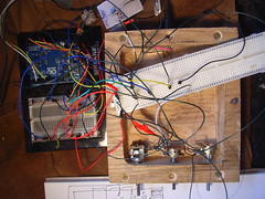
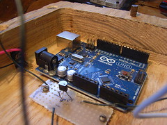
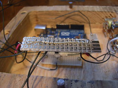
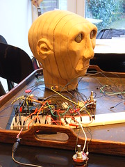
Wanting to complete my automata-based reading lamp, but having had a lot of servo burnouts, I am trying to prevent the servo getting any power in between position changes. This should greatly reduce the risk of heating.
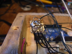
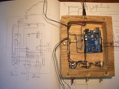
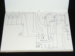
struggling with the circuit.

If I us digital pin outputs, an output voltage can easily be turned to HIGH (5V) or LOW (0V), but only seems to work with no servos attached. When they are attached the voltage is only 2.5V.

not sure what I'm doing wrong

valPot1 = analogRead(potPin1);            // reads the value of the potentiometer (value between 0 and 1023)
  if ((valPot1 <= midLow)or (valPot1>= midHigh)) {
     digitalWrite (PowerPin,HIGH); //turn on power to servos briefly only at point of writing to allow movement;
     digitalWrite (ledPinJoystick,HIGH);
    // potActive1=true;
    valPot1 = map(valPot1, 150, 900, 0, 179);     // scale it to use it with the servo (value between 0 and 180)
 
    myservo.write(valPot1);                  // sets the servo position according to the scaled value
 
    delay(delay_val);
 digitalWrite (PowerPin,LOW); //turn off power to servos again once moved to reduce heating effect;  
  }
  else {
    digitalWrite (ledPinJoystick,LOW); // signal that value is in mid-range dead-spot - used to turn off LED that indicates joystick activity;
    digitalWrite (PowerPin,LOW); //turn off power to servos when inactive;
  }

Wednesday, 23 November 2011

Head needs a controller

The remote control automata reading lamp head needs a suitably daft controller.
It uses a playstation 2 analog joystick as the input device,
Playstation 2 controller wired to Arduino
but this needs something more anatomical to skin it with. It has been suggested a hand would be rather ironically appropriate. It should look like this, but match the MDF finish of the head

image from wpclipart.com

Saturday, 1 October 2011

Making high power (3W) LED eyeballs for the automaton

New eyeballs

The eyeballs in my automaton head work OK, but are woefully underpowered. Time to make some new ones!
This is looking at the basic starting point of a detachable eyeball from the front look towards the back. The hole is where the housing goes.
Detachable eyeball
The housing is the (more or less) parabolic reflector from a torch
Hacking parts from a torch
The eyeball is made detachable by adding a rubber grommet, which allows it to be pushed tight onto the servo control rod. The rubber friction holds it tightly in place.
Detachable eyeball
The eyeballs are ready to attach, although not cosmetically finished yet.
New High power LED eyeballs
Here they are hooked up to the breadboard to test how they work
New High power LED eyeballs
They are remarkably more powerful. Each LED is 3W, which is pretty bright. It hurts t0 look straight into them
High power LED eyeballs being tested
You can see how much more powerful the 3W led is on the left
Comparing high power LED eyeballs

Here the test is to see how much light they give off in total darkness. The head is meant to be a bedside/reading lamp with remote control directable beam, via the eyeballs.

Testing shows this is plenty of light!
High power LED eyeballs being tested
Close-up it's easier to see how much light is given off.
High power LED eyeballs being tested

Tuesday, 27 September 2011

Hacking VHS players for spare electronics parts

VHS video - electonics parts recycling This is the inside of a dead VHS video recorder/player. It turns out it is still full of lots of old-school eletronics. Sure, there are lots of PCBs, but due to the mecahnical nature of video players with their big motors and stuff, there are a lot of useful connectors in there, as well as some high power resistors, transistors, loads of potentiometers and so on. A good way to pick up cheap parts.
Here is a handy 10 pin connector with the wiring all nicely connected. Try soldering anything remotely as neat as this, and you will see how useful a ready made is!
Remote control connector for Automata head
Here it is connected up to the breadboard jump leads coming off the arduino
Remote control connector for Automata head
And here it is fed into the underside of the head, from the board
Automata head connected