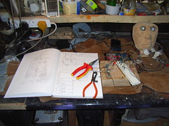
Testing the pots...
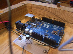
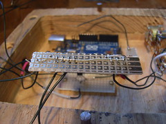
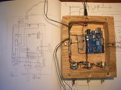
The arduino screwed down in place, in final location inside base.
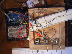
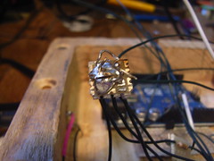
Connecting up all the wires that need to be at the positive (+5V) voltage, by threading through a circuit board, to be soldered together.
Final +5V "rail" with all +5v connections soldered together

Connecting up all the wires that need to be at earth (ground), by threading through a circuit board, to be soldered together.

Final earth (ground) "rail" with all earth connections soldered together
The final circuit in place in the base, next to the conceptual circuit layout diagram.
No comments:
Post a Comment