Schematic and circuit unit
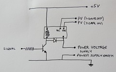
Having got the relay circuit to work on the testbed breadboard, it was time to build it into a unit...Here's the schematic and the finished board together.

The relay circuit is very simple. This relay uses a 5V voltage to trigger the switchover. The transistor has no current flowing as default, which means the output power voltage is sent to one connector (middle right block).
Applying a signal voltage HIGH to the input, causes a current to flow in the transistor and therefore through the relay switching coil. This changes the power voltage to the alternate relay output pin.
Earthing
There are two separate circuits in a relay. There is a high current power switched circuit, which here is 12V. There is also a coil circuit that switches this power voltage from one output to another. Here the switch circuit is driven at 5V.The earth of the two relay circuits should be connected or natural differences in voltage levels can cause unexpected problems.
Completed circuit unit

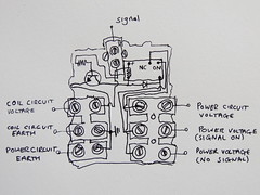
The left hand image shows the circuit in it's final form on the board with connectors. The red indicates power voltages with black as earth.
The left hand connectors are the coil circuit power in, the coil earth and an earth connector for the power circuit linked to the coil earth.
The right hand connectors are for the power supply voltage (top, all red), the power voltage with signal switched on (also all red), and power voltage with signal off (black and red), respectively.
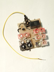
The right hand image shows the underside with connectors and mounting screws.
The top, black connector block is for the signal in.
This unit is now ready to be deployed as required.
There are a couple of mistakes in your circuit. Firstly, the diode should be connected from the transistor's collector terminal to the 5V power supply. In other words, it should be in parallel with the relay coil, but normally non-conducting (the arrow opposing the flow of conventional current from + to -).
ReplyDeleteSecondly, the advantage of using a relay is that you don't need to connect the ground of the switched circuit to the ground of the Arduino. In fact, if you were switching mains voltages, connecting them would be dangerous.
Thanks. Well spotted. The earth thing is an especially good point. Here it is for convenience, but you're right.
ReplyDelete