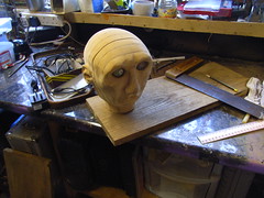
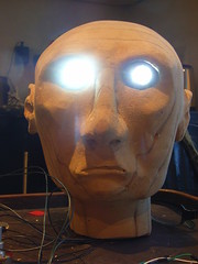
Having finished the head, it seemed poor to use a plastic plug. What better than a wooden plug?
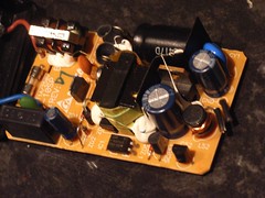
Initially I started trying to take apart the plastic casing of the transformer, which looked like this. Unfortunately, the supply failed, which I believe to be due to fusin printed circuit connections with solder while trying to solder a new lead onto the circuit board. FAIL!
Having destroyed one supply, another was found in the shed. This was fitted up with an oak casing
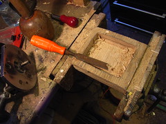
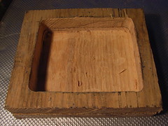
This was made from two short pieces of oak plank, with a cavity taken out with an electric router
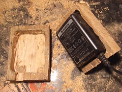
The two halves together look like this
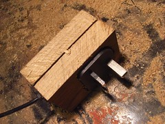
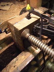
These are not flush. To do so they needed to be sanded together as one piece. This would only work once glued together. Here theyare in the vice with cramps attached (one traditional iron screw cramp, and one metal/plastic ratchet cramp)
The processes involved when I make stuff: sculpting, programming, electronics, carving, moulding, etc. Mostly puppets, automata, sculpture, occasionally furniture, interactives, food, etc. Usually fairly detailed and image-led. Please reuse any ideas, tips, thoughts and approaches.
Wednesday, 29 February 2012
Friday, 24 February 2012
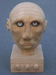
Head is finally finished...
Finally the head is just about ready...
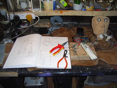
I amused myself looking up the original drawing....
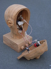
Here's what's inside the face...
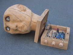
...and the arduino control circuit under the base...
All that really remains is to make the power supply...
I amused myself looking up the original drawing....
Here's what's inside the face...
...and the arduino control circuit under the base...
All that really remains is to make the power supply...
Labels:
#rosemarybeetle,
arduino,
automata,
carving sculpted
Sunday, 19 February 2012
Moving automaton head electronics from test-bed to in situ base
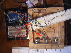
On the bench. Trying to transfer the patched electronics from the nice easy patch-cable connections of the test bed to the real, hard-wired circuit in the final location of the base of the automaton head.
Testing the pots...
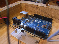
The arduino screwed down in place, in final location inside base.
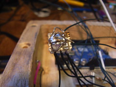
Connecting up all the wires that need to be at the positive (+5V) voltage, by threading through a circuit board, to be soldered together.
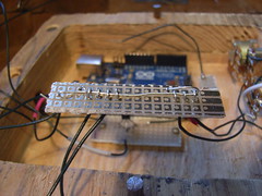
Final +5V "rail" with all +5v connections soldered together
Connecting up all the wires that need to be at earth (ground), by threading through a circuit board, to be soldered together.
Final earth (ground) "rail" with all earth connections soldered together
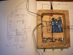
The final circuit in place in the base, next to the conceptual circuit layout diagram.
Friday, 17 February 2012
Fitting arduino electronics into the automaton base in practise
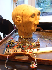
Having finalised the circuit, it needs to move from test bed to final location with the base the automaton sits on... Here is what the arduino test bed looks like. Spaghetti everywhere. Most of which is just convenience wiring to help.
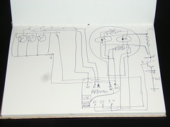
This is the circuit drawn out in beautiful hand-drawn pen.
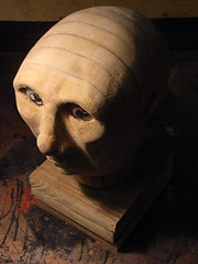
This is the head on it's base (not finished here)
This is the box and how it opens out showing the space available
So here is the tidied up circuit diagram showing approximate location of the electronics. Next to it, is the box with the control pots in place.
Labels:
#rosemarybeetle,
arduino,
automata,
carving,
electronics,
sculpted,
sculpture
Thursday, 16 February 2012
Making a base for the automaton head
Measuring out base from an oak plank
Drilling pilot holes for recess, that will form internal housing for electronics. I love working with oak - such a great smell, yum :)
Cleaning up internal cavity
The internal space for electronics, finished
With lid...
This is the head on it's base
Thursday, 2 February 2012
New simpler electronics
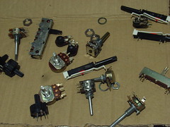
I have bought a fine bag of potentiometers. How sad!
They are presumably culled from some beautiful old stereos, but anyway...
Here is the more or less final circuitry. I have decided not to tackle the power issue about servos only getting current on a change of signal. This is a cop out, but it's time to move on.
Power
however, I have introdcued a transistor to step up the current to the eyeball LEDs.
This does make them a little brighter
Labels:
#rosemarybeetle,
arduino,
automata,
electronics
Subscribe to:
Posts (Atom)