http://www.instructables.com/id/How-to-make-a-remote-control-sentient-web-puppet-b/
Twitr_janus - several months of plotting through code and physical creation finally got written up on Instructables :)
Some condensing of the basic elements needed to make it plus inevitable cross-refencing back here...
The processes involved when I make stuff: sculpting, programming, electronics, carving, moulding, etc. Mostly puppets, automata, sculpture, occasionally furniture, interactives, food, etc. Usually fairly detailed and image-led. Please reuse any ideas, tips, thoughts and approaches.
Showing posts with label twitr_janus. Show all posts
Friday, 15 February 2013
Tuesday, 6 November 2012
What is @twitr_janus - A summary overview, November 2012 for MCN attendees
This post is an updated summary of what @twitr_janus is, and what it demonstrates
This is mainly aimed at attendees at the Museums Computer Network conference, Seattle, 2012, especially the Slack Day hacking workshop, where this cutey will be being demonstrated live. (if I can put it back together again)
Firstly, here is @twitr_janus in cabin baggage ready to be checked in as hand luggage. I am not sure it will be allowed on board the aircraft...

@twitr_janus is a live physical avatar - a puppet that can be controlled remotely over the Internet using the data sources of common web services like Google Drive and Twitter and direct web-enabled services such as Skype. It is a (very) crude alpha prototype that demonstrates several simple ways to remotely interact physically using web data services or piggybacking the connectivity of audio/visual web services.
Its real point though, is to demonstrate how real-time sensory interaction can be achieved by hacking together feeds, APIs or just features of common freebie web services. It can see you, hear you, talk to you and move its eyes to watch you. That's not creepy at all.
To control @twitr_janus, data is sent to it over the Internet using free web tools that have interactive elements. These include sending a tweet in a specific Twitter account and creating custom forms that piggyback the form processing script of a Google spreadsheet, but many other web services could be used.
At the other end of the web, the structured data is retrieved so it can be manipulated. This is done using the open source Processing language running on a connected computer. Processing can parse (strip out selective data) from open RSS feeds and/or APIs.
The data is then converted into physical action. An open source text-to-speech library for Processing is used to generate speech from text data. It can speak either tweets from its Twitter account, or from the contents of a field in a Google spreadsheet.
@twitr_janus uses the open source hardware platform Arduino to convert other data to physical motion. Eye control is achieved by an Arduino sketch loaded on the board, which reacts to data parsed from feeds from a Google spreadsheet. This signal data controls the position of two servos that direct the focus of its stare.
Its jaw is lip-synched to speech output by converting the analogue audio signal levels into a control signal for a car-door lock actuator motor. An audio amplifer is used to create asignal large enough to detect, and the Arduino sketch triggers a relay power circuit for the actuator based on signal peaks. It also has LEDs to indicate the last source of its control data.
Finally it can see and hear via a webcam. It does this using web video software Skype. This can be remotely activated using the correct settings in Skype
The important point is simply that almost any modern web service will use, or often be built upon, a data publishing model. Because these web services have built-in data publishing features, such as APIs (application programming interface) or feeds such as RSS, they convert the human input tools into predictable data output that can be manipulated. None of this requires you to set up any infrastructure.
This principle can be used to hack new things together. It's all very enjoyably Frankenstein. @twitr_janus is just a specimen beast, created to illustrate this with a physical example. It simply demonstrates some possibilities beyond obvious web front end stuff, of hacking data from current open source or freely available web services, to create physical interaction.
It's crude, often breaks and has cost the lives of two Arduino boards, at least five servos and one vintage glue gun (RIP), but it does show how web data doesn't have to be just on-screen.
Other things that could be quickly prototyped using this method can easily be imagined such as:
(with apologies to my professional developer colleagues for the state of this hackery!)
The basic (and very rough) code is available for forking/hacking/recycling as you see fit. Note, this will be only the last working version:
This is mainly aimed at attendees at the Museums Computer Network conference, Seattle, 2012, especially the Slack Day hacking workshop, where this cutey will be being demonstrated live. (if I can put it back together again)
Firstly, here is @twitr_janus in cabin baggage ready to be checked in as hand luggage. I am not sure it will be allowed on board the aircraft...
What is @twitr_janus?
@twitr_janus is a live physical avatar - a puppet that can be controlled remotely over the Internet using the data sources of common web services like Google Drive and Twitter and direct web-enabled services such as Skype. It is a (very) crude alpha prototype that demonstrates several simple ways to remotely interact physically using web data services or piggybacking the connectivity of audio/visual web services.
Its real point though, is to demonstrate how real-time sensory interaction can be achieved by hacking together feeds, APIs or just features of common freebie web services. It can see you, hear you, talk to you and move its eyes to watch you. That's not creepy at all.
How does this work?
At the other end of the web, the structured data is retrieved so it can be manipulated. This is done using the open source Processing language running on a connected computer. Processing can parse (strip out selective data) from open RSS feeds and/or APIs.
The data is then converted into physical action. An open source text-to-speech library for Processing is used to generate speech from text data. It can speak either tweets from its Twitter account, or from the contents of a field in a Google spreadsheet.
@twitr_janus uses the open source hardware platform Arduino to convert other data to physical motion. Eye control is achieved by an Arduino sketch loaded on the board, which reacts to data parsed from feeds from a Google spreadsheet. This signal data controls the position of two servos that direct the focus of its stare.
Its jaw is lip-synched to speech output by converting the analogue audio signal levels into a control signal for a car-door lock actuator motor. An audio amplifer is used to create asignal large enough to detect, and the Arduino sketch triggers a relay power circuit for the actuator based on signal peaks. It also has LEDs to indicate the last source of its control data.
Finally it can see and hear via a webcam. It does this using web video software Skype. This can be remotely activated using the correct settings in Skype
WTF?
This principle can be used to hack new things together. It's all very enjoyably Frankenstein. @twitr_janus is just a specimen beast, created to illustrate this with a physical example. It simply demonstrates some possibilities beyond obvious web front end stuff, of hacking data from current open source or freely available web services, to create physical interaction.
It's crude, often breaks and has cost the lives of two Arduino boards, at least five servos and one vintage glue gun (RIP), but it does show how web data doesn't have to be just on-screen.
Other things that could be quickly prototyped using this method can easily be imagined such as:
- Tweetometer for marketing campaigns. Use Twitter data about your campaign tags to make a physical thermometer go up and down to indicate success. (e.g. Trend ranking, number of retweets, etc.)
- Animatronic avatar interaction to query collections or events databases. If data can be extracted, it can be spoken
- Physical puppet automatically announces new events as they appear in the api of your events database
- etc. etc.
Free code and stuff...
The basic (and very rough) code is available for forking/hacking/recycling as you see fit. Note, this will be only the last working version:
Processing control sketch (version 15)
(polls web feeds from Google and Twitter to extract data)
Github code download
PDF version
(polls web feeds from Google and Twitter to extract data)
Github code download
PDF version
Arduino sketch (used to manipulate data and/or analogue signals into physical actions)
Github code download
PDF version
Github code download
PDF version
There are detailed posts about the specific physical build of @twitr_janus in the archive if this blog. Physical build notes crop up in back posts here on makingweirdstuff (interspersed with other nonsense)
E.g. Posts about building eyeballs
Labels:
arduino,
avatar,
MCN,
Processing,
puppets,
twitr_janus
Tuesday, 23 October 2012
Making servo mounts inside Twitr_janus' puppet head
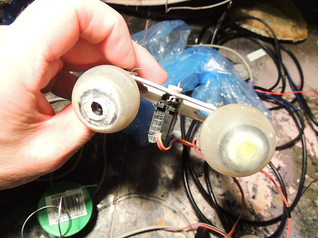
Twitr_janus' eyeballs are controlled by two servos. Like all eyeballs the two eyeballs must move as a pair (well maybe not chameleon's, granted!). This is done by fixing two eyesockets into the skull. Each one can contain an eyeball with a positioning rod at the rear of the eyeball. The rods for the two eyeballs are then fixed together in such a way that they can only move up down togther or left right together.
Here's what this looks like from the front (this is the skull only. It doesn't have skin yet)
The eyeballs were made from old deodorants. For details on making eyeballs and sockets from deodorants, see this post, and this Instructuble (animatronic head reading lamp).
Here's the underside showing the two servo mounts. The one on the left is the left/right rig. The one on the right is the up down cable controller
The main cranium of the skull here is laminated papier mache, which is strong, and can take a self-tapping screw to affix the plastic servo mounts.
The main construction is in making the rig. This is a collapsing parallelogram frame that fixes the rotation of the control rods into one plane, seen here from above, showing the fulcrums (pivots) maded from split pins with washers. The servo is in the middle and is fixed to one cross-beam, with the end of the servo-horn connected by a free pivot to the other. This is actually not a good design, as the arc it sweeps is not even.
From the front, you can see the servo body

Here it is inside the head. The servo rotates in the left/right direction, causing lateral shearing, but in the up/down direction, the rod moves with the rods. The eyeball/left/right servo rig is clearly visible on the left here, and the cable attached to the rig is the up down mover, attached to the horn of the second servo
The mounts are made from square section PVC cable conduit, which can be cut to shape with tin snips and folded with long-nose pliers.
Here is the up/down servo

Here's what this looks like from the front (this is the skull only. It doesn't have skin yet)
The eyeballs were made from old deodorants. For details on making eyeballs and sockets from deodorants, see this post, and this Instructuble (animatronic head reading lamp).
Here's the underside showing the two servo mounts. The one on the left is the left/right rig. The one on the right is the up down cable controller
The main cranium of the skull here is laminated papier mache, which is strong, and can take a self-tapping screw to affix the plastic servo mounts.
The main construction is in making the rig. This is a collapsing parallelogram frame that fixes the rotation of the control rods into one plane, seen here from above, showing the fulcrums (pivots) maded from split pins with washers. The servo is in the middle and is fixed to one cross-beam, with the end of the servo-horn connected by a free pivot to the other. This is actually not a good design, as the arc it sweeps is not even.
From the front, you can see the servo body
Here it is inside the head. The servo rotates in the left/right direction, causing lateral shearing, but in the up/down direction, the rod moves with the rods. The eyeball/left/right servo rig is clearly visible on the left here, and the cable attached to the rig is the up down mover, attached to the horn of the second servo
The mounts are made from square section PVC cable conduit, which can be cut to shape with tin snips and folded with long-nose pliers.
Here is the up/down servo
Thursday, 18 October 2012
Hacking out an audio amplifier for a text-to-speech puppet voicebox
@Twitr_janus needs a voicebox. This will do two things:
Below left is where is he output plug comes out of the amplifier. The output cable was cut to expose the wires (below right)
This cable is coaxial. The outer sheath copper mesh is the earth level, with a sheathed inner copper core
Below left is what the stripped cable looks like. Below right with the oscilloscope lead attached
And on the left here is the signal trace. Each square is 1V.

This is what will be used to drive the Arduino. The output which is here driving the oscilloscope will be attached to the Arduino analog input. The Arduino will convert the analog audio level into digital data. In fact a number between 0 and 1024.
The Arduino script will send pulses to a relay if the signal peak is higher than a preset threshold level.
In practise the jaw will trigger to move, if there is a peak speech output (e.g. a plosive B, etc)
This is done in Arduino with a function that polls the analog input, something like this. (This example uses variables that would normally be declared elsewhere in the sketch.)
void jawTrigger () { // jawTrigger is a function to be called in the Arduino loop()
This is not able to simulate how a real mouth looks when speaking, which will change shape depending on the phonemes in the speech. Here the mouth movement is synced to an audible peak, which the audience will hear as they see movement, and the brain will believe it is speaking the words.
The PC amplifer has two speaker boxes. One master speaker with an amplifier in it and one slave speaker that is driven by it.
Old long-handled, sheet-metal-cutting shears make light work of even such a thick plastic casing (below left)
Below right is the amplifier extracted from the box
- Amplify the Processing text-to-speech output from a feeble PC audio speaker to a dedicated speaker in the puppet
- Provide a voltage level that is high ebough to use as an analog input to be detected by the Arduino board, to power the speech to jaw motion sync
Below left is where is he output plug comes out of the amplifier. The output cable was cut to expose the wires (below right)
This cable is coaxial. The outer sheath copper mesh is the earth level, with a sheathed inner copper core
Below left is what the stripped cable looks like. Below right with the oscilloscope lead attached
And on the left here is the signal trace. Each square is 1V.
This is what will be used to drive the Arduino. The output which is here driving the oscilloscope will be attached to the Arduino analog input. The Arduino will convert the analog audio level into digital data. In fact a number between 0 and 1024.
The Arduino script will send pulses to a relay if the signal peak is higher than a preset threshold level.
In practise the jaw will trigger to move, if there is a peak speech output (e.g. a plosive B, etc)
This is done in Arduino with a function that polls the analog input, something like this. (This example uses variables that would normally be declared elsewhere in the sketch.)
void jawTrigger () { // jawTrigger is a function to be called in the Arduino loop()
jawPeakVol = analogRead(analogPin); // turns voltage from amplifier signal wire into a number between 0 and 1024
if (jawPeakVol >= jawThresholdVol) {
digitalWrite (jawRelayPin, HIGH);
// trigger the relay to make the jaw motor move if the voltages peaks above a preset threshold (jawThresholdVol)
} // end if
else if (jawPeakVol < jawThresholdVol) {
digitalWrite (jawRelayPin, LOW);// trigger the relay to make the jaw motor return to default rest position if the voltage drops below the threshold
} // end else if
} // end jawTrigger
This is not able to simulate how a real mouth looks when speaking, which will change shape depending on the phonemes in the speech. Here the mouth movement is synced to an audible peak, which the audience will hear as they see movement, and the brain will believe it is speaking the words.
The speaker is stereo. There are two outputs
The lead above is the feed from the master box to the slave box.
Inside the master box is the speaker that will be the voicebox itself. This was removed from the box, and the box was then cut up to use as a mount
Old long-handled, sheet-metal-cutting shears make light work of even such a thick plastic casing (below left)
Below right is the amplifier extracted from the box
Labels:
#arduino,
#rosemarybeetle,
arduino,
audio,
twitr_janus
Tuesday, 2 October 2012
Hacking a Microsoft LifeCam to make a video eyeball
Warning this post contains scenes of open-webcam surgery and the hacking of roll-on deodorant bottles...
To interact with people via the Internet, Twitr_janus needs to be able to see.
Here is a webcam-enabled eyeball, made from a Microsoft LifeCam, a deodorant ball and a pen refill...

Twitr_janus needs one eye to be able to see who is looking at it. The eye was made from a Microsoft LifeCam.
This can be driven by Skype. Skype allows you to start a video call with a remote computer, which means the eyeball can be turned on at will from anywhere (and using Skype apps on phones etc.!). And so...
The LifeCam is a reasonably good webcam. The camera is housed in a convenient cylinder that readily fits a sawn off deodorant ball!
The ball was hacked from a standard roll-on deodorant ball
The hole can be made even and the edges smoothed off by rubbing on sandpaper on a flat surface.
Having tested the camera eyeball in situ for physical movement, it was clear that the camera housing was far too bulky and the cam needed removing from its casing. Amazingly a quick trawl of the web found a very detailed step by step description of how to do this.
Respect to Gary Honis, whose Astrophotography and Digital Imaging website had a whole article detailing all the tricky screws things needed to get the camera and drive board out of the shell
http://ghonis2.ho8.com/lifecam/lifecam1.html
This started simple, but ended up like the jumble on the right after about half an hour
Eventually the camera was extracted from the case and looked like this

The eyeball was given a cornea, made from an old torch lens, trimmed to size with a file and glued in...
Here is the camera in the ball. This is fascinating to pugs...
The last remaining thing was to add a means by which the eyeball could be moved. To do this a rod needed to be added.
The casing of the camera was operated on and with a bit of simple metalworking


>
Until a beautiful eye was made, thus!
To interact with people via the Internet, Twitr_janus needs to be able to see.
Here is a webcam-enabled eyeball, made from a Microsoft LifeCam, a deodorant ball and a pen refill...
Twitr_janus needs one eye to be able to see who is looking at it. The eye was made from a Microsoft LifeCam.
This can be driven by Skype. Skype allows you to start a video call with a remote computer, which means the eyeball can be turned on at will from anywhere (and using Skype apps on phones etc.!). And so...
The LifeCam is a reasonably good webcam. The camera is housed in a convenient cylinder that readily fits a sawn off deodorant ball!
The ball was hacked from a standard roll-on deodorant ball
The hole can be made even and the edges smoothed off by rubbing on sandpaper on a flat surface.
Having tested the camera eyeball in situ for physical movement, it was clear that the camera housing was far too bulky and the cam needed removing from its casing. Amazingly a quick trawl of the web found a very detailed step by step description of how to do this.
Respect to Gary Honis, whose Astrophotography and Digital Imaging website had a whole article detailing all the tricky screws things needed to get the camera and drive board out of the shell
http://ghonis2.ho8.com/lifecam/lifecam1.html
This started simple, but ended up like the jumble on the right after about half an hour
Eventually the camera was extracted from the case and looked like this
The eyeball was given a cornea, made from an old torch lens, trimmed to size with a file and glued in...
Here is the camera in the ball. This is fascinating to pugs...
The last remaining thing was to add a means by which the eyeball could be moved. To do this a rod needed to be added.
The casing of the camera was operated on and with a bit of simple metalworking
Until a beautiful eye was made, thus!
Labels:
#rosemarybeetle,
eyeball,
twitr_janus,
webcam
Subscribe to:
Posts (Atom)