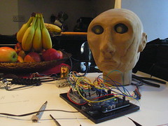
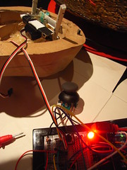
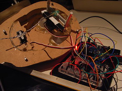
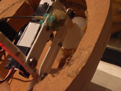
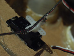
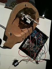
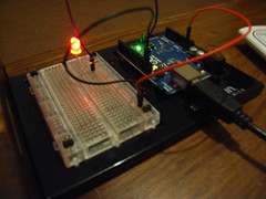
THis is the latest version of lamp_head - the arduino test code for controlling my automaton lamp/head/thingy
a lot of this is redundant, but there are 2 functions
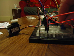
1. "readPots()" uses potentiometers to vary the voltage to analogue inputs, then converts this to a digital number then uses that to control servo position. This would allow 2 controls (up/down and left/right)
2. "manualUp() uses a switch to decide whether to incrementally increase the digital output . In this case, if the switch is on, then the output goes up, if it is off it sticks at the latest value. This could be used with a joystick, so that pushing up increases the UP/Down values incrementally, and pushing down would reduce it correspondingly. This would need four such inputs to be set up
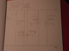
circuit diagram
>>>>>>>>>>>>>>>>> here starts the sketch >>>>>>>>>>>>>>>>
/*
Lamp head version 3 - this programme is to control the automaton lamp head
Andrew Lewis September 2011
This code is in the public domain.
1. Turns on and off a light emitting diode(LED) connected to digital pin 13, when a switch attached to pin 2 is turned on.
The circuit:
* LED attached from pin 13 to ground
* pushbutton attached to pin 2 from +5V
* 10K resistor attached to pin 2 from ground
*/
// constants won't change. They're used here to
// set pin numbers:
// @@@@@@@@@@@@@@@@ stuff to do with LED controls
const int switchPin1 = 2; // the number of the pushbutton pin
const int ledPin = 10; // the number of the LED pin
int buttonState = 0; // variable for reading the pushbutton status
int delay_val_LED=10 ;
// @@@@@@@@@@@@@@@@@@@
// @@@@@@@@@@@ This defines aspects fo the digital control
const int pinUp =11; // constant to set the UP input to be digital pin 11 (d11)
// this
int delayer=10; // sets delay for digital control
int valUp=90; //set manual number conrol UP at mid point by default =90
int upPin=11; //defines up eyeball control value pin to be digital pin 11
// @@@@@@@@@@@@@@@@@@@@@ end
#include
// includes servo class file (out of the box from arduino.cc - TVM!)
Servo myservo; // create servo object to control a servo
Servo myservo2; // create second servo object
int potPin1 = 0; // analog pin used to connect the potentiometer (pot 1) for servo 1
int valPot1; // variable to read the value from the analog pin for servo 1
int potPin2 = 1; // analog pin used to connect the potentiometer for servo 2
int valPot2; // variable to read the value from the analog pin for servo 2
int delay_val=15; //the value of the servo wait delay fro both servos
int val_lamp=0; // lamp output value for fading up
// @@@@@@@@@@@@@@@@@@@@@@@@@@@@
void setup() {
// initialize the LED pin as an output:
pinMode(ledPin, OUTPUT);
pinMode(switchPin1, INPUT); // initialize the pushbutton pin as an input:
pinMode(pinUp, INPUT); // sets digital PIN (defined by pinUp) to be the input for increases that make eyes go up UP
// attach servos
myservo.attach(5); // attaches the servo on pin 9 to the servo object
myservo2.attach(9); // attaches second servo to pin 8 to second servo object
}
void loop(){
// lamp controls
// fade_on();
turn_on();
manualUp(); //Include this function to check for digital increases in UP value (this would be one of four needed to control eitehr a joystick or other four point controller
//readPots()// Include this function in the loop for dual analogue controls (1 potentiometer per servo)
}
// define manual increase meter
void manualUp ()
{
if (digitalRead(pinUp)==LOW){
valUp--;
valUp = constrain (valUp,0,179);
delay (delayer);
}
myservo.write(valUp);
}
///define potentiometer function
void readPots()
{
// read the state of the pushbutton value:
// servo controls @@@@@@@@@@@@@@@@@@@@@
// Servo 1 -------------
valPot1 = analogRead(potPin1); // reads the value of the potentiometer (value between 0 and 1023)
valPot1 = map(valPot1, 180, 800, 0, 179); // scale it to use it with the servo (value between 0 and 180)
myservo.write(valPot1); // sets the servo position according to the scaled value
delay(delay_val);
// ------------ servo 1 end
// servo 2 ------------------------
valPot2 = analogRead(potPin2); // reads the value of the potentiometer (value between 0 and 1023)
valPot2 = map(valPot2, 180, 800, 0, 179); // scale it to use it with the servo (value between 0 and 180)
myservo2.write(valPot2); // sets the servo position according to the scaled value
delay(delay_val);
// ------------ servo 2 end
// end servo controls @@@@@@@@@@@@@@@@@@@@@@ */
}
void fade_on () {
if ( digitalRead(switchPin1)==HIGH) {val_lamp--;} //reduce if high
else if (digitalRead(switchPin1)==LOW) {val_lamp++;}
val_lamp = constrain (val_lamp,0,255);
analogWrite (ledPin, val_lamp);
delay(delay_val_LED);
}
void turn_on () {
if ( digitalRead(switchPin1)==HIGH) {val_lamp=255;} //reduce if high
else if (digitalRead(switchPin1)==LOW) {val_lamp=0;}
val_lamp = constrain (val_lamp,0,255);
analogWrite (ledPin, val_lamp);
delay(delay_val_LED);
}
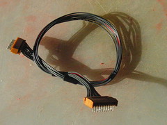
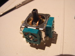
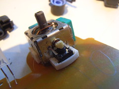
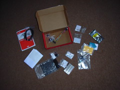
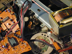 This is the inside of a dead VHS video recorder/player. It turns out it is still full of lots of old-school eletronics. Sure, there are lots of PCBs, but due to the mecahnical nature of video players with their big motors and stuff, there are a lot of useful connectors in there, as well as some high power resistors, transistors, loads of potentiometers and so on. A good way to pick up cheap parts.